The Mark Ortiz Automotive
CHASSIS NEWSLETTER
Presented free of charge as a service
to the Motorsports Community
September 2010
Reproduction for free use permitted and encouraged.
Reproduction for sale subject to restrictions. Please inquire for details.
WELCOME
Mark Ortiz Automotive is a chassis consulting service primarily serving oval track and road racers. This newsletter is a free service intended to benefit racers and enthusiasts by offering useful insights into chassis engineering and answers to questions. Readers may mail questions to: 155 Wankel Dr., Kannapolis, NC 28083-8200; submit questions by phone at 704-933-8876; or submit questions by e-mail to: markortizauto@windstream.net. Readers are invited to subscribe to this newsletter by e-mail. Just e-mail me and request to be added to the list.
WHEN ONE IS A VERY SMALL ANIMAL: CONSIDERING AN RC CAR
After reading through some
of the newsletters you have written about vehicle suspensions etc., I was
hoping I could ask you a few questions about an rc model car. Since a year ago
I have a new hobby in racing with remote control cars. These are electric
motor powered by battery 4wd models with
independent suspension. Perhaps you have seen them before, but just in case, I
have included a few pictures in the email. At the moment I work as a
structural engineer but since starting the hobby I have been catching up on my
original automotive engineering degree and dusting off my vehicle dynamics books.
The car actually races "on
road" on tracks especially suited to their size with proper very fine,
smooth, tarmac surfaces.
The size scale is supposed to be 1/10 scale. Wheelbase is about 254mm. Track
width is about 167mm in the front, with the rear usually 1-2mm narrower. The
minimum weight limit is 1350 grams. The cars are constant 4-wheel drive with a
locked front axle and a rear differential. Depending on the type of motor and
controller used, the top speed can reach anywhere between 60km/h to 115km/h. During
the races I compete in, on the track with the largest straight we reached
90km/h. So the speed is far from scale.
Perhaps these cars are
completely different to their full size counterparts but I still find it
fascinating to see some of the numbers that come up when I check them. For
instance: roll centres below ground; sprung cg below the unsprung cg height; a
locked front axle (both wheels rotate at the same speed); natural frequency of
the suspension in the order of 8-12Hz; pressureless rubber tires filled with a
foam insert, and tire additives to increase grip of the tires are allowed.
The unsprung mass c.g. is above the sprung mass c.g. due to the fact that the tire diameter is 63mm, with the tire, bearings, and uprights being the parts making up the unsprung at 31.5mm above ground, while the unsprung mass major components are the batteries, motor, servo and speed
control module. These are all located directly on the carbon chassis plate. With a ride height of 5mm, the sprung c.g. is located about 20-25mm above ground.
I worked my way through
determining the roll centres, basic wheel rates, load transfer in a general 1g
corner, and roll stiffness distribution to better understand how the car works.
I was hoping that
by better understanding the engineering part I could find my advantage over the
younger natural talent drivers who might not be so proficient in this area.
Now I got a little bit puzzled over a few things in the suspension. It is
supposed to be a H-arm with camber link system for all four wheels. But how to
find the antiforces in this type suspension? The inside point of the H-arm can
be angled by shimming more (or less) on one side of the mounting points
(mounting point you can seen in the rear view image). This should create
anti's but also change the arm travel (wheelbase change and track width
changes).
Would the changes to track width and wheelbase be more influence compared to
the antis created (if antis are created as this is the original question)? Secondly,
these cars frequently use droop limitation by screws in the H-arm that
restrict how far the arm is allowed to travel down to the
chassis plate.
I understand the droop limitation effect in the accelerating and braking condition,
but what will happen in roll? How will the wheel loads respond when the inside
wheel reaches its droop limitation point while the outside wheel is still
suspended by the spring? When this happens is the chassis roll completely
determined by the compression of the outside spring?
I hope you can give me some help in order to decipher what makes these cars
work, and why some things are done this way in these cars.
I will not attempt to present myself as an expert on these cars. I have never encountered them before, much less raced one or advised anybody who raced one. But it is fascinating to consider some of the things that happen when one tries to drastically scale a mechanism up or down.
In general, small machines, or animals, will have better "scale performance" than their larger counterparts. Some effects don't change with scale at all; some change dramatically.
For example, the fact that ants can lift astonishing percentages of their body weight is primarily due to their small size. If there were giant ants as depicted in '50's horror movies, they probably couldn't walk, or even breathe adequately to support their body mass. Mice have skinny little legs and pudgy little bellies, yet can jump amazing multiples of their own height or length.
These effects result from the fact that a muscle's cross-sectional area, which largely determines its strength, increases with the second power of scale, while its volume, which largely determines its mass, increases with the third power of scale.
Very small creatures (spiders, small insects) can be dropped off a roof and not get hurt, because they reach aerodynamic terminal velocity at such a low speed that it's like they have parachutes on. If we
take a given engine cylinder and scale it up, it has dramatically less valve and port area per unit of displacement, and will theoretically make less power per unit of displacement.
These effects occur because an object's surface-to-volume ratio goes up as it gets smaller. Taking a sphere as a representative example, frontal area and surface area both increase with the second power of scale, while volume (hence mass, if the sphere is solid) increases with the third power of scale.
If we could scale a car down to 1/10 of its size, without having to completely rethink the entire machine, it would have 1/100 of its previous surface area and frontal area, and only 1/1000 of its previous mass. It would have ten times as much valve area per unit of displacement. It would have ten times the brake swept area per unit of weight. If the static deflection of the tires stayed in scale, the car would have ten times the contact patch area per unit of weight. This would require a tire vertical spring rate 1/100 that of the full-size car.
Likewise, to keep the suspension's static deflection in scale (1/10 as great), the wheel rate in ride would have to be 1/100 as great, while the ¼-car sprung mass would be 1/1000 as great. Undamped natural frequency is entirely a function of absolute (not scale) static deflection. It varies inversely with the square root of static deflection. So if the static deflection is 1/10 as great, the natural frequency is greater by a factor of √10, or 101/2, which is about 3.16. In fact, no matter what the 1/10 scale car actually weighs, if the static deflection in Earth's gravity is to scale, the natural frequency will be about 3.16 times as great as that of its full-scale counterpart.
So a 1/10-scale car with a natural frequency of 8 Hz has a scale static deflection corresponding to a full-scale car with a frequency of 2.5 Hz. A 1/10-scale car with a natural frequency of 12 Hz has a static deflection corresponding to a full-scale one with a frequency of 3.8 Hz. Assuming that the bumpiness of the track surface really is to scale, those would be downforce car numbers.
What, then, of the likely downforce characteristics of a 1/10-scale car?
The density of these cars, if they are close to the minimum weight of 1350 grams, is remarkably similar to that of a full-scale car. A full-scale one would be 1350 Kg, or 2970 lb. So the car's mass is about 1/1000 of a full-size car's, while its aerodynamic surface area is 1/100 as large. The RC car has ten times the aerodynamic surface area per unit of mass. And it goes about ½ to 1/3 as fast, meaning that its scale speed is 3 to 5 times that of the full-size car.
The Reynolds number for the RC car is only about 1/20 to 1/30 that of the full-size car, so air flow patterns may be fairly dissimilar, but just using the crude assumption that aero forces are proportional to the square of speed, and proportional to surface area, the RC car, going ½ as fast as the full-scale one should generate about (1/2)2 * (1/100), or .0025 times the downforce, while having .001 times the mass. That would mean that the RC car has two and a half times the downforce,
relative to its mass. This would be comparing the RC car at 90 kph to a full-scale car at 180 kph (112 mph), or the RC car at 115 kph to a full-scale car at 230 kph (144 mph).
Or, for 1/3 the speed, the downforce is (1/3)2 * (1/100), or .0011 times as great. That would be a ratio of downforce to mass, for 90 kph or 115 kph, similar to a full-size car at 270 kph (169 mph) or 345 kph (216 mph) respectively.
This means that the RC car should have roughly 2.5 to 1.1 times the suspension displacement due to downforce, compared to the full-size car, for a given static deflection. But note: that's actual displacement, and actual static deflection, not scale! In other words, a 1/10-scale car with a model production sports car body, with just a wing and a splitter, can create enough downforce to require LMP-range scale static deflections. So that's where the need for those wheel rates comes from.
With a serious downforce body, and/or big wings, the car could probably generate some prodigious accelerations, but it would probably then need frequencies upwards of 25 Hz just to keep the floor pan off the pavement. It isn't so much that the RC car generates dramatically more downforce for its weight; it's more that the suspension deflection caused by the downforce must be so much smaller, due to the limited travel available in such a small car.
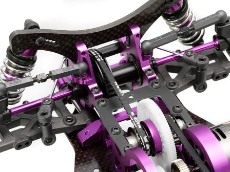
Looking at the photos, the roll centers do appear to be a bit below ground, and there appears to be little or no camber recovery in roll – perhaps even negative camber recovery. That could probably be improved upon, unless you are confined to spec parts.
If camber recovery is zero, that means that for roll and lateral load transfer analysis, you can treat the unsprung mass as sprung. It has about the same rate of y-axis (transverse) displacement with respect to the contact patch, per degree of roll, as the sprung mass has. Even if you had 100% camber recovery, and none of the unsprung mass rolled with the sprung mass (for instance, if you had a beam axle), you would not need any different method of calculation than you'd use with the sprung mass c.g. above the unsprung mass c.g.'s.
That lower arm/upper link suspension is similar to the rear suspension on an E-Type Jaguar. When the lower arm pivot axes are horizontal, all longitudinal anti's are zero. When the axes tilt in side view, the side view force line tilts at the same angle. So to add some rear anti-squat, you raise the front mount and lower the rear one. You also get slight changes in the longitudinal anti's with vehicle pitch.
I see there are no friction brakes at the wheels, so I take it that braking is done electronically: you have "inboard brakes".
So the geometric part is simple. However, to calculate percent anti-squat, anti-lift, and anti-dive, you need to know the distribution of the longitudinal ground-plane forces, and there is considerable uncertainty concerning those. You have no center differential, and no front one, but you say there's a
rear one. Looking at the photos, I can't imagine how they package that rear one – that looks like a spool – but in any case, when you have fewer than three diffs and four driven wheels, the ground
plane forces at the individual wheels depend heavily on how the wheels work with and against each other as grip varies and as the car goes around turns. As a default, you could just calculate percent
anti's assuming equal ground plane forces at all wheels, but you should be aware that this may not model actual operation very accurately.
As long as the axes are close to horizontal, the longitudinal anti's are all close to zero anyway. Since no torque acts through the suspension linkage as a whole (although there are torsional loadings on the lower arm), you have only "thrust anti's" and therefore you inevitably do have some wheelbase change with suspension displacement when you have some anti. This isn't necessarily a problem.
You will also have some track change with suspension movement if you have any lateral anti's. For most purposes, a little track increase with suspension compression is good. When the roll center is below ground, you have a bit of track decrease with suspension compression.
As to the effect of droop limiting, it is no different than in a full-size car. When the inside wheel reaches the limiter, the suspension wheel rate goes to near-infinity, and the suspension can only roll by compressing the outside wheel suspension. I have addressed the effects of this at length in some previous newsletters (Sept. 2007, Feb. 2010). I also have an article in the works based on K&C testing of a droop-limited car at Morse Measurements in Salisbury, NC. Stay tuned to Racecar Engineering for that.